Build a People Counter for $30 Using an ESP8266 and NodeMCU
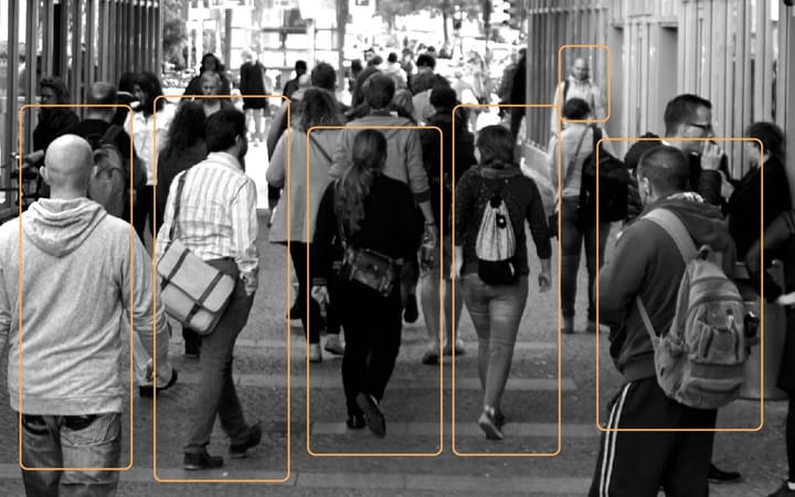
A people counter is a device used to measure the number of bodies traversing an entrance, hallway, street corner, etc. If you need to know how many people exist in a space – this is your simple solution. Typically used in retail stores, large events, and smart office buildings. This counting technology has provided insights to both the number of bodies in an environment and how they behave. Imagine you’re the store owner; this counter can alert you to daily visitors, the walking paths are taken, most frequent stopping points, and how long a person lingers in a place. Wouldn’t you like to know what materials/products gain the most attention? With this insight, a marketer can reposition products geographically to increase awareness. This, benefiting your customer’s needs and your bottom line.
In this guide, you will learn how to build your own home-made people counter. Also included are instructions for your newly collected data to be utilized via Ubidots, an application enablement platform.
Materials required
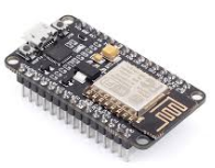
- ESP8266 NodeMCU
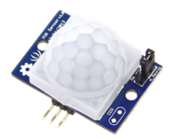
- PIR Motion Sensor
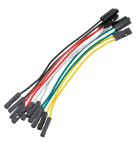
- Female – Female Wires
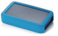
- Plastic Protection Case
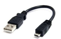
- MicroUSB Cable
Wiring and Casing
As you can see, the motion sensor has three pins: V+, Ground, and a third for outputs signal (“1” = movement, and “0” static environment). First, plug the cables straight to the pins of your NodeMCU, follow the table and diagram below:
| NodeMCU | PIR Sensor | NodeMCU | LED | |
|---|---|---|---|---|
| GND | GND | GND | GND | |
| D6 | OUT | D4 | VCC | |
| 3.3V | VCC |
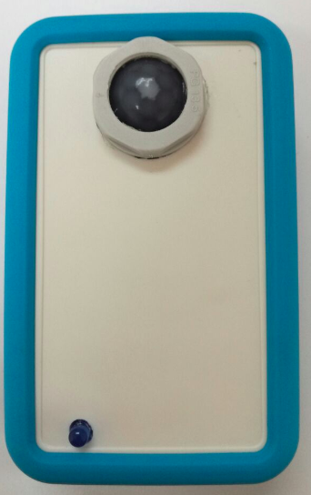
Because the PIR motion sensor is very sensitive to movement, I used a jumper switch behind it to set the lowest sensibility. I also painted over the lens corners to focus on one specific space instead of omnidirectional. (Don't limit yourself, you can explore and innovate) The results of these few extra minutes of work result in the friendly, contained device pictured below.
With the case and device pieced together, we now need to connect with Arduino IDE.
To start, connect your NodeMCU to your computer’s port using the micro USB
NOTE: If you do not already have the Arduino IDE, click here to download
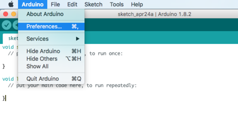
1.- Open the Arduino IDE, select File -> Preferences. Next, input the following URL into the Additional Board Manager URLs text box. You can add multiple URLs by separating them with commas, if needed.
http://arduino.esp8266.com/stable/package_esp8266com_index.json
NOTE: If you’re a Mac user, please note that Arduino contains different drop down functions compared to Windows operating system. Also, you will need to install the following driver to be able to upload your NodeMCU.
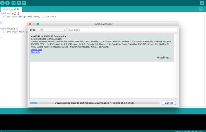
2.- Open Boards Manager from Tools -> Board menu and install ESP8266 platform. To simply find the correct device, search ESP8266 within the search bar.
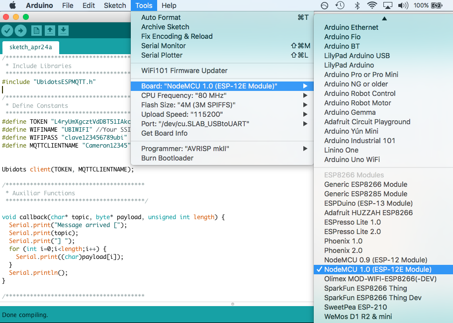
3.- Select your NodeMCU 1.0 (ESP-12 Module) from Tools > Board menu.
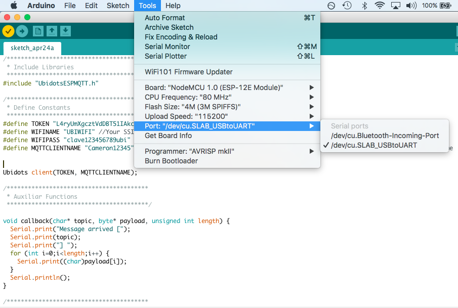
Additionally, we need to be able to communicate with the NodeMCU; select the correct port com for your device.
Go to Tools > Port > Select the appropriate PORT for your computer/device connection.
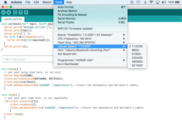
Also, to keep everything running fast and smooth – let’s make sure the upload speed is optimized to 115200.
Go to Tools > Upload Speed > 115200:
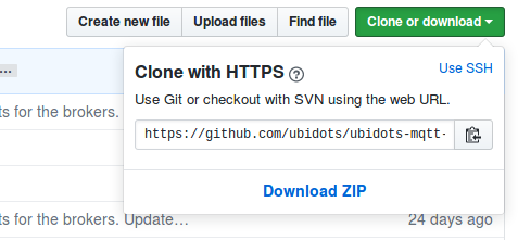
4.- Next we need to download the Ubidots MQTT ESP library from Github. To do this, open the MQTT ESP library here, download the library by clicking the green button called “Clone or download” and select “Download ZIP“.
5.- Now move back to your Arduino IDE, click on Sketch -> Include Library -> Add .ZIP Library
6.- Select the .ZIP file of ubidotsMQTTESP and then “Accept” or “Choose”
If successful, you will receive this message below in the Arduino IDE confirming your library:

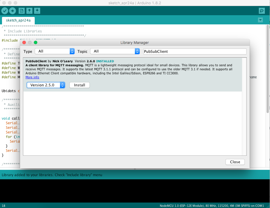
7.- Next, go to Sketch/Program -> Include Library -> Library Manager and install the PubSubClient library. To simply find the correct library, search PubSubClient within the search bar.
8.- Close the Arduino IDE and open it again. This restart is required. Please do not miss this step!!
Now it is time to start coding 🙂
Copy the code below and paste it into the Arduino IDE.
Once you have copied the code, you will need to assign the parameters: Wi-Fi name and password, plus your individual unique Ubidots TOKEN. If you don’t know how to locate your Ubidots TOKEN, please reference this article below.
// Made by: Maria Carlina Hernandez
/****************************************
 * Include Libraries
 ****************************************/
#include "UbidotsESPMQTT.h"
/****************************************
 * Define Constants
 ****************************************/
#define TOKEN "..." // Your Ubidots TOKEN
#define WIFINAME "..." //Your SSID
#define WIFIPASS "..." // Your Wifi Pass
#define DEVICE "pir-sensor" // Assign the device label
#define VARIABLE "motion" // Assign the variable label
#define LED 2
#define SENSOR D6

uint8_t counter=0;
unsigned long state = 0;

Ubidots client(TOKEN);

/****************************************
 * Auxiliar Functions
 ****************************************/

void callback(char* topic, byte* payload, unsigned int length) {
  Serial.print("Message arrived [");
  Serial.print(topic);
  Serial.print("] ");
  for (int i=0;i<length;i++) {
    Serial.print((char)payload[i]);
  }
  Serial.println();
}
/****************************************
 * Main Functions
 ****************************************/

void setup() {
  // put your setup code here, to run once:
  Serial.begin(115200);
  pinMode(SENSOR, INPUT);
  pinMode(LED, OUTPUT);
  client.wifiConnection(WIFINAME, WIFIPASS);
  client.begin(callback);
  }

void loop() {
  // put your main code here, to run repeatedly:
  if (!client.connected()) {
      digitalWrite(LED, LOW);
      client.reconnect();
      digitalWrite(LED, HIGH);
  } else {
      digitalWrite(LED, HIGH);
  }

  uint8_t sensorValue = digitalRead(SENSOR);
  bool flag = false;

  if(sensorValue>0){
    for(uint8_t wait=0; wait<=4; wait++){
      sensorValue = digitalRead(SENSOR);
      Serial.println(sensorValue);
      if(sensorValue==1){
      counter++;
      }
      if(counter>3){
        flag = true;
      }
      delay(500);
    }
  }

  Serial.println("sending data");
  uint8_t value;
  if(flag){
    value = 1;
    client.add(VARIABLE, value);
    client.ubidotsPublish(DEVICE);
  }else{
    value = 0;
    if(state == 10000){
      client.add(VARIABLE, value);
      client.ubidotsPublish(DEVICE);
      state = 0;
    }
  }
  state++;
  client.loop();
  counter = 0;
}
Once you pasted the code and updated the WiFi parameters, you must Verify this within the Arduino IDE. To do this, in the top left corner of our Arduino IDE you will see the below icons. Choose the Check Mark icon to verify any code.

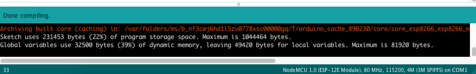
Once the code is verified, you will receive a “Done compiling” message in the Arduino IDE.
Next, your have to upload the code into your NodeMCU. To do this, choose the right-arrow icon beside the check mark icon.

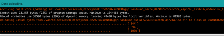
Once the code is uploaded, you will receive a “Done uploading” message in the Arduino IDE.
Now your sensor is sending data to the Ubidots Cloud!
Status LED
Once your code is uploaded, the onboard LED will alert you the devices connectivity.
- LED on -> Ok, device connected and sending data.
- LED blink (1 second) -> Trying to reconnect. Lost the connection. No acces to internet.
- LED off -> Device not connected
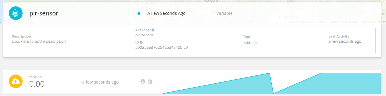
Management of the data in Ubidots
If your device is correctly connected you will see a new device created within your device section in your Ubidots application. The name of the device will be “sensor-pir“, also inside the device you will see the variable created called “motion.“
If you desire to change your device and variable names to a more friendly one, please reference this article
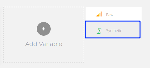
Next, to count the number of people your device is detecting, we need to create a new derived variable to be able to manage the data and count the number of people detected.
Click on “Add variable” and select “Synthetic“:
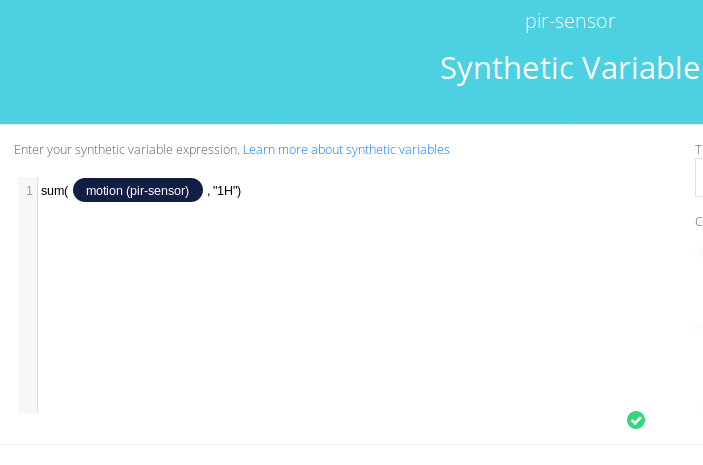
Select the device called “pir-sensor” and the variable “motion” then, compute the sum every time set as you desire ( 1 minute; 1 hour; 1 day) to get the number of people detected. Press Save and assign a name for the variable. Your formula will look a little something like the following:
sum(motion, "1H")
Once your variable is created, you will receive the number of people detected in that new synthetic variable. Below is an illustration of the final result:
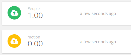
Result
This project educates administrators and decision makers to the number of people passing through a particular space and how they operate. Please note not every person will be detected due to limitations of the motion sensor. The line of sight is important for us humans and machines also struggle with this too. But we are working on it!
Now it is time to create a dashboard to control and manage the variables of your own People Counter. To learn more about Ubidots widgets and events, check out these video tutorials and sign up for free today!