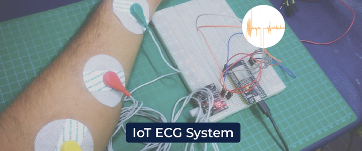
Build an IoT ECG (Electrocardiogram) System with an AD8232 + ESP32 to record your heart's electrical activity
Heart disease has been a major population’s illness for many years. The World Health Organization (WHO) study also shows that most people die from heart diseases. Therefore, this disease cannot be taken lightly, for this reason, healthcare devices and monitoring systems are designed to track disease professionally.
We know these diseases can be prevented by analyzing and monitoring the ECG signal at the initial stage. Based on this, I decided to work in this project to start monitoring my ECG signal using Ubidots IoT Development Platform.
In this article, we’ll deploy the very basic starting and running the AD8232 heart rate monitor. Then we'll show you how to connect it to your favorite micro-controller and how to create visualizations using an IoT Platform.
What is the AD8232?
The AD8232 is a neat little chip that measures the electrical activity of the heart. This electrical activity can be expressed as an ECG or an electrocardiogram. An electrocardiogram is used to help diagnose various heart diseases. (More info: The datasheet can be found here.)
The plan is setup the AD8232 board to perceive the ECG signal, to start producing the output signal from the AD8232 board. The output signal will give approximately 1.5 volts, producing a 1k sample/second. Then, these signals will be sent over the USB from the Arduino, so we can check it over the Serial Monitor and Ubidots.
Without nothing more to say, let’s get started!
Requirements
- Ubidots account
- Arduino Uno / Mega / Nano
- ECG module (AD8232)
- ECG electrode - 3 pieces
- ECG electrode connector - 3.5 mm
- DATA Cable
- Jumper Wires
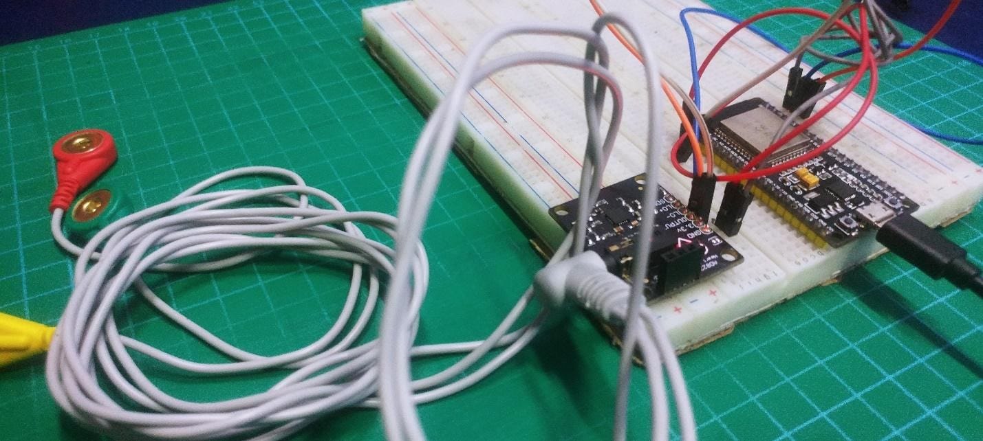
Wiring
Follow the diagram and table below to start wiring the devices required:
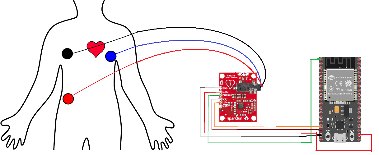
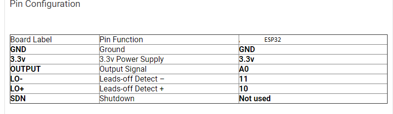
Once your hardware is properly wired. Let's continue with the ESP32 configuration.
Setting up ESP32 with Arduino IDE
Please Follow the steps below and then you can able to program the ESP32 with the Arduino IDE.
1. Click on File >Preferences
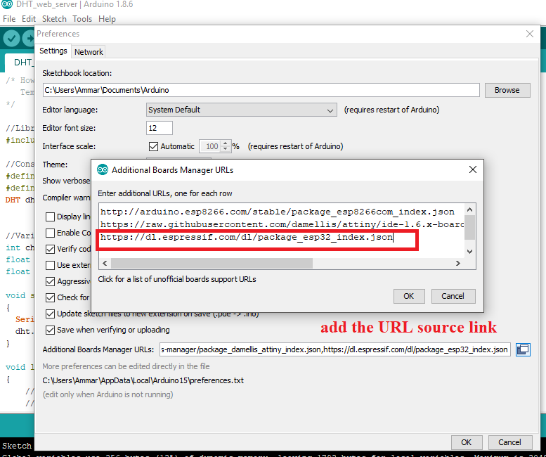
2. into the “Additional Board Manager URLs” field assign the URL below. You can add multiple URLs, separating them with commas if needed.
https://dl.espressif.com/dl/package_esp32_index.json
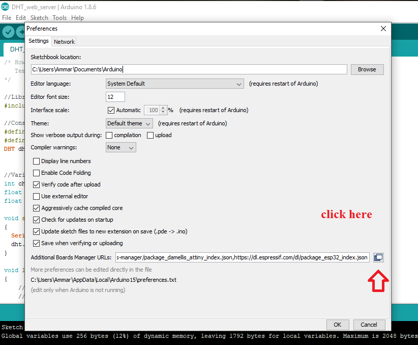
3. To save the changes made, make sure of press the OK button.
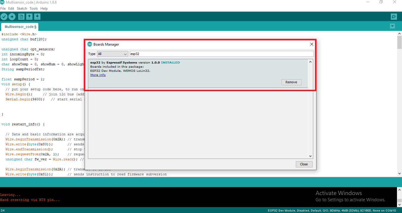
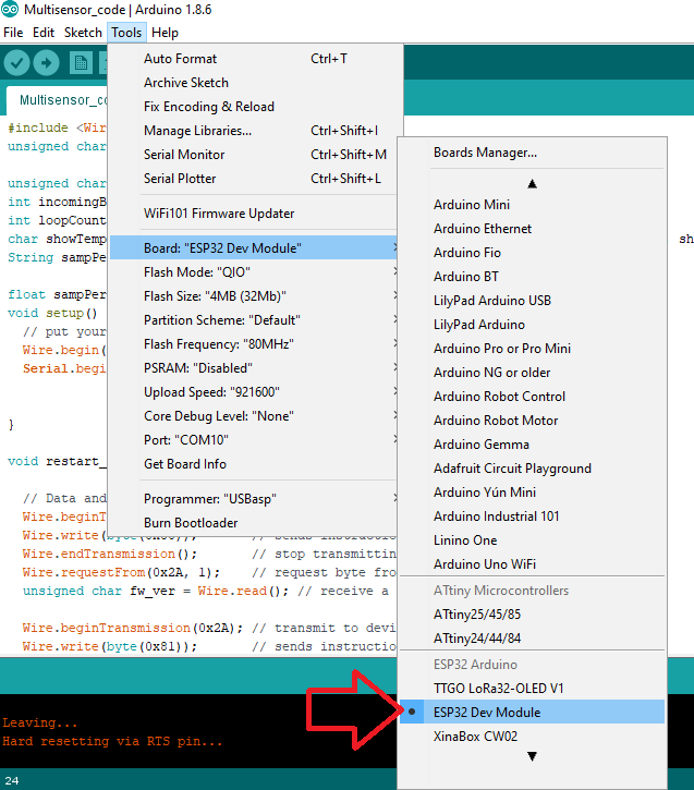
4. Now, add the ESP32 platform in the Arduino IDE. To do this, Click Tool> Board> Board Manager
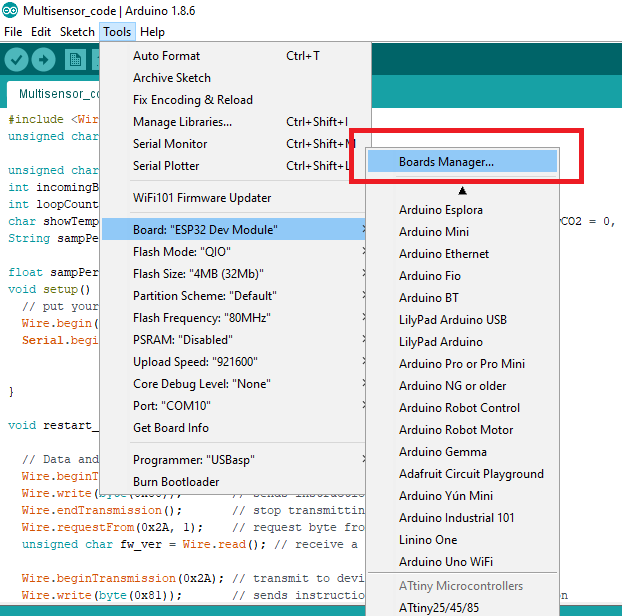
5. In the Search bar, write “ESP32” and install the latest package.
Upload Source Code
1. With the proper set up of the ESP32 in the Arduino IDE, upload the following code into the board after assigning the parameters required on it.
- WIFISSID: Your WiFi SSID
- PASSWORD: Your WiFi password
- TOKEN: Your Ubidots TOKEN
- MQTT_CLIENT_NAME: Your own 8-12 alphanumeric character ASCII string.
Source code
To refer to this sample code, as well as other IoT Projects tutorials check out this repository.
/****************************************
 * Include Libraries
 ****************************************/
#include <WiFi.h>
#include <PubSubClient.h>

#define WIFISSID "your wifi name" // Put your WifiSSID here
#define PASSWORD "your wifi password" // Put your wifi password here
#define TOKEN "your token" // Put your Ubidots' TOKEN
#define MQTT_CLIENT_NAME "1234a5d6798" // MQTT client Name, please enter your own 8-12 alphanumeric character ASCII string;
                                           //it should be a random and unique ascii string and different from all other devices

/****************************************
 * Define Constants
 ****************************************/
#define VARIABLE_LABEL "sensor" // Assing the variable label
#define DEVICE_LABEL "esp32" // Assig the device label

#define SENSOR A0 // Set the A0 as SENSOR

char mqttBroker[]  = "industrial.api.ubidots.com";
char payload[100];
char topic[150];
// Space to store values to send
char str_sensor[10];

/****************************************
 * Auxiliar Functions
 ****************************************/
WiFiClient ubidots;
PubSubClient client(ubidots);

void callback(char* topic, byte* payload, unsigned int length) {
  char p[length + 1];
  memcpy(p, payload, length);
  p[length] = NULL;
  Serial.write(payload, length);
  Serial.println(topic);
}

void reconnect() {
  // Loop until we're reconnected
  while (!client.connected()) {
    Serial.println("Attempting MQTT connection...");

    // Attemp to connect
    if (client.connect(MQTT_CLIENT_NAME, TOKEN, "")) {
      Serial.println("Connected");
    } else {
      Serial.print("Failed, rc=");
      Serial.print(client.state());
      Serial.println(" try again in 2 seconds");
      // Wait 2 seconds before retrying
      delay(2000);
    }
  }
}

/****************************************
 * Main Functions
 ****************************************/
void setup() {
  Serial.begin(115200);
  WiFi.begin(WIFISSID, PASSWORD);
  // Assign the pin as INPUT
  pinMode(SENSOR, INPUT);

  Serial.println();
  Serial.print("Waiting for WiFi...");

  while (WiFi.status() != WL_CONNECTED) {
    Serial.print(".");
    delay(500);
  }

  Serial.println("");
  Serial.println("WiFi Connected");
  Serial.println("IP address: ");
  Serial.println(WiFi.localIP());
  client.setServer(mqttBroker, 1883);
  client.setCallback(callback);
}

void loop() {
  if (!client.connected()) {
    reconnect();
  }

  sprintf(topic, "%s%s", "/v1.6/devices/", DEVICE_LABEL);
  sprintf(payload, "%s", ""); // Cleans the payload
  sprintf(payload, "{\"%s\":", VARIABLE_LABEL); // Adds the variable label

  float sensor = analogRead(SENSOR);

  /* 4 is mininum width, 2 is precision; float value is copied onto str_sensor*/
  dtostrf(sensor, 4, 2, str_sensor);

  sprintf(payload, "%s {\"value\": %s}}", payload, str_sensor); // Adds the value
  Serial.println("Publishing data to Ubidots Cloud");
  client.publish(topic, payload);
  client.loop();
  delay(500);
}
2. Verify your code within the Arduino IDE. To do this, in the top left corner of our Arduino IDE you will see the "Check Mark" icon; press it to verify your code.
3. Upload the code into your “ESP32 Dev Kit”. To do this, choose the "right-arrow" icon beside the "check mark" icon.
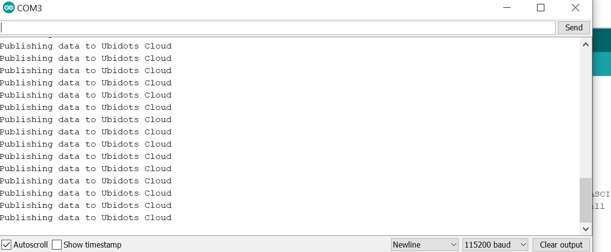
4. After uploading the code, open the Serial Monitor and you will see how the devices is establishing the connection to WiFi, and to the MQTT broker.
Let’s Setup Ubidots
Let’s setup an Ubidots’ Dashboard. To create it, go to the Dashboard section (Data > Dashboard)
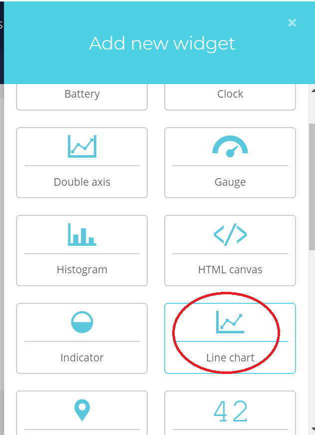
1. Then, press on “Add new Widget”, and select your widget.
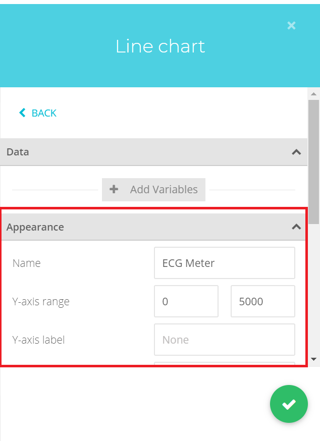
2. Select the type of widget desired to be displayed. In my case, I choose the “Line Chart”:
3. Then, select the variable desired to display the data. Ubidots allows you assign a customize widget name, color, period of data to be displayed and much more. I invite you to explore all the options for the different widget types. To finish the widget creation, press the green icon.
Now you are able to monitor your ECG signal and other variables remotely thanks to Ubidots IoT Application Development Platform.