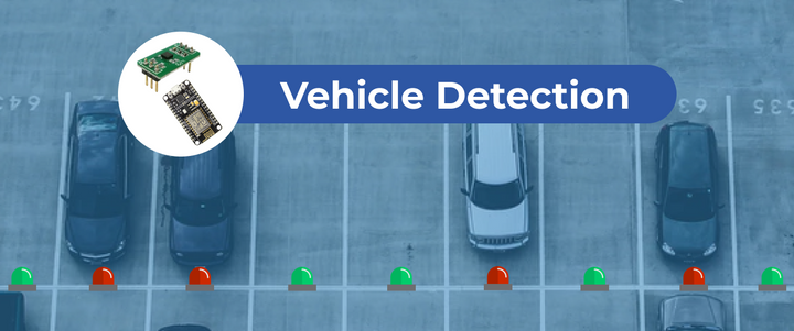
[2/3] From the hardware to the cloud: Testing MMC5883MA
Have you ever thought about developing your own IoT application from scratch, but you didn’t know where to start? Good news, here you'll learn how to do it! Stay on a tune about the project progress [here].
This is the second of a series of articles through which I will describe the process of developing my own IoT application from scratch. If you have not read part 1 yet, I recommend you do it first, so you can understand the project’s context and catch up on the considerations taken into account to select the technologies and components needed to build the first prototype.
To be able to build a prototype, it becomes necessary to know the operation details and technical specifications of each component. From my experience, I consider that the first (and maybe the most important step) is to understand the main aspects of the modules' datasheet. Afterwards, I recommend carrying out individual tests with each one of them to understand their behavior.
Keeping all of this in mind, I decided to start with the most critical part of the prototype: the sensors. The reason is simple: it's necessary to make sure that the selected sensors are actually able to detect the presence of a vehicle, besides from comparing them in order to find out which is the most adequate to fill the application requirements and objectives.
Throughout this article, I will describe the process carried out to evaluate the behavior of the magnetic sensor MMC5883MA and its capacity to detect the presence of a vehicle in a parking spot. At the end, the test results will be shown and analyzed.
About the components
The MMC5883MA is a low power 3-axis magnetic sensor which can communicate, through an I2C interface, with an external microcontroller. By writing and reading certain specific registers from the sensor, the microcontroller can configure the operation mode and start the measurement process, besides obtaining the measurements data.
For this test, I'm using the evaluation version of the MMC5883MA sensor, called MMC5883MA-B, because superficial components cannot be tested so easily. As I needed to build a prototype first, most of the components should be connected through a breadboard and the MMC5883MA-B, which allows me to do so without requiring extra time and work.
To be able to carry out the test, the first step was to select a microcontroller to collect the data generated by the sensor. However, as the focus of the test lies in the analysis of the sensor behavior, not the microcontroller behavior, a good option can be to choose a microcontroller simple to program, to reduce the time and complexity of the experiment. In brief, I needed to find a simple and practical microcontroller (or development board), with an I2C interface, which also had the capability to send the sensor data to the Ubidots platform to be stored and processed there.
Keeping all of this in mind, I decided to use a NodeMCU ESP8266 as the microcontroller. This Arduino compatible development board is based on the WiFi module ESP8266 and it's very popular among Internet of Things applications due to its practicality. This device has a variety of communication interfaces, including I2C. All of these features makes it appropriate for being used in the experiment.
Test description
The experiment consisted of taking periodic measurements of the magnetic field on a parking spot simulating real conditions, this is, with vehicles entering and leaving it. The sensor data should be sent in real-time to the Ubidots platform and then analyzed to identify if there were any change in the behavior of the measurements that could be related to the vehicle presence.
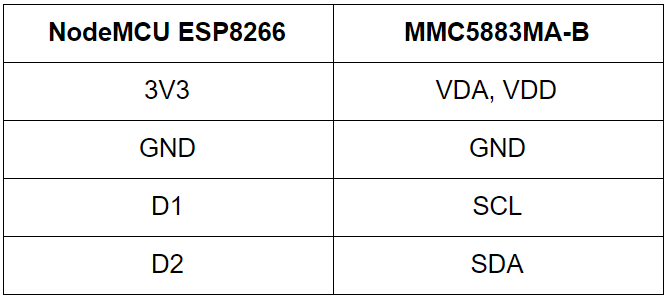
The MMC5883MA-B has to be connected with the NodeMCU ESP8266 through the I2C port. These connections can be easily made with the help of a breadboard. The NodeMCU module has to be properly configured to be able to access a WiFi network and send data to Ubidots. The last detail before starting the test was to provide a power supply to the modules, in order to make them portable. As the modules' work voltage is 3.3 volts, it should be enough to use two AA batteries of 1.5 volts each one, connected in series. The resulting connections are shown in the diagram below.
Time to code
Since the NodeMCU is an Arduino compatible board, it can be programmed through the Arduino IDE. The Arduino code must implement two main tasks:
- Sensor data acquisition.
- Data post in the Ubidots platform.
The part of the code in charge of reading the data from the sensor and decoding it to obtain the magnetic field measurement was written based on the datasheet of the MMC5883MA, where the sensor’s registers are explained in detail. Here, the Arduino library Wire.h was very helpful to achieve the I2C communication.
The part of the code in charge of setting up the WiFi connection and sending the data to the Ubidots platform is based on the Ubidots tutorial "Connect a NodeMCU ESP8266 to Ubidots over HTTP". To learn how to configure the Arduino IDE to program the NodeMCU board, I recommend to follow step 1 found in the tutorial.
The resulting code can be found at this Github repository.
Test results
After completing the configurations explained above and ensuring that the NodeMCU was reading the data and sending it to Ubidots successfully, I placed the breadboard on the floor of the parking spot, proximately in the position marked with the green X in the image below.
To start the test, I parked a car and left it there for a few minutes. After that, I moved the car out and waited for a couple of minutes before repeating the process. Keep in mind that the sensor was taking the measurements periodically, around every two seconds. I repeated the same process several times and finished the test.
Previously, I configured a dashboard in my Ubidots account to ease the visualization of the sensor data. After finishing the test, I reviewed the graphs in my dashboard and this is what I found:
As I was analyzing the data, I noticed that there were some significant changes in the z-axis measurements. The first one occured when the magnitude of the magnetic field in the z-axis increased (marked with the "1" in the image above); the second one was when the magnitude decreased again (marked with the "2" in the image above). It's important to notice that the magnitude of the data taken between these points stands proximately around the same value.
Keeping all of this in mind, is possible to conclude that the changes marked as 1 and 2 correspond to the moments when I parked the car (1) and moved it again (2). In addition, the measurements taken between them mean the time while the car was parked. This behavior in the measurements was repeated again in the point marked as 3.
The experiment outcome implies that, with the MMC5883MA, a vehicle presence can be detected through the changes in the magnetic field measurements, which will be more considerable in one of the axis, in this case, the z-axis. To sum things up, when there is a car in the parking spot, the magnetic field measurement will be higher than when it is alone. According to the difference between these values, it's possible to define a threshold to take a decision about the vehicle's presence.
The next objective to achieve is to carry out similar experiments with the other sensors. At the end, the outcomes have to be compared in order to find out which of the sensors is the most appropriate to build the project final prototype.
If you want to know how the other experiments results, keep an eye on the next posts.