Siemens SIMATIC S7 PLC as Modbus TCP Server: A Quick Tutorial
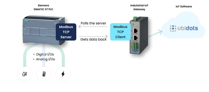
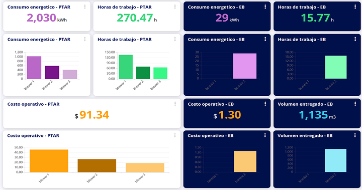
The Siemens SIMATIC S7-1200 is more than just a programmable logic controller (PLC); it’s a cornerstone of industrial automation. The Modbus protocol, known for its simplicity and ease of implementation, is highly relevant here as it facilitates industrial communication and data transmission within factory automation. By configuring it as a Modbus Server, you can share the data with an IoT gateway configured as Modbus Client to take data beyond the factory floor and achieve remote monitoring by even sending the PLC data into the cloud. In this guide, we’ll walk you through the entire process, from programming the PLC to simulating communication with a Modbus client.
Are you ready to unlock the full potential of your Siemens S7-1200? Let’s dive in!
Introduction to Modbus and PLCs
Modbus is one of the most widely used protocols in industrial settings. Most industrial PLCs, including the Siemens SIMATIC S7-1200, support multiple communication protocols, such as Profinet and Modbus. Modbus itself comes in two common variants: Modbus RTU (operating on a master-slave architecture over serial communication) and Modbus TCP (utilizing a server-client model over Ethernet).
In this tutorial, we’ll demonstrate how to configure the Modbus TCP IP S7 1200 as server and communicate with devices across an industrial network. We will also use a Modbus simulator to test the setup.
Requirements
Hardware Requirements
1. Siemens S7 PLC (we’re using the S7-1212C DC/DC/DC model, but any S7 series with Modbus functionality will work)
2. Profinet/Ethernet cable
3. Power supply for the PLC
Software Requirements
- TIA Portal V16 (for Siemens PLC programming and configuration)
- MODBUS ClientX (a Modbus TCP client for simulating communication)
Hardware Setup
To begin, connect the power supply to the Siemens SIMATIC S7-1200 PLC. Use a Profinet or Ethernet cable to link the PLC’s Ethernet port to your PC or network switch. This connection is essential for enabling TCP/IP communication between the PLC and your Modbus client.
Configuring the S7-1200 PLC in TIA Portal
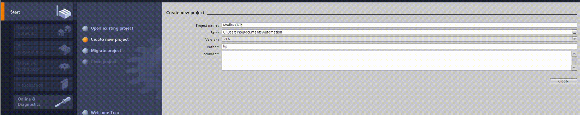
- Launch TIA Portal and create a new project in “Project View.”
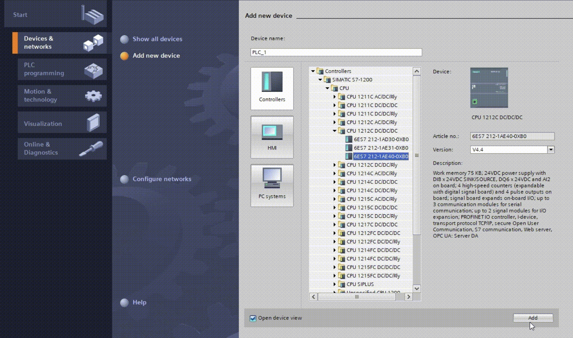
- Select “Configure a Device” and then “Add New Device.” Choose your Siemens S7-1200 model and the correct firmware version before clicking “Add.”
In the project tree, you can navigate and manage the components of your project, such as accessing properties and configuration settings.
Important Note: If the PLC already contains an existing program, ensure you use the same firmware and TIA Portal version. Otherwise, it’s best to upgrade to the latest available version.
Setting up the S7-1200 PLC as Modbus TCP Server
- Navigate to the “Main (OB1)” block in the “Project View” to start creating a ladder logic diagram.
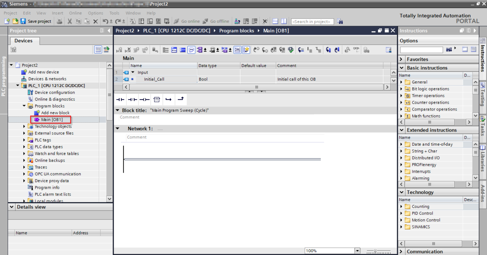
- In the “Instruction” window on the right, go to Communication -> Others -> Modbus TCP.
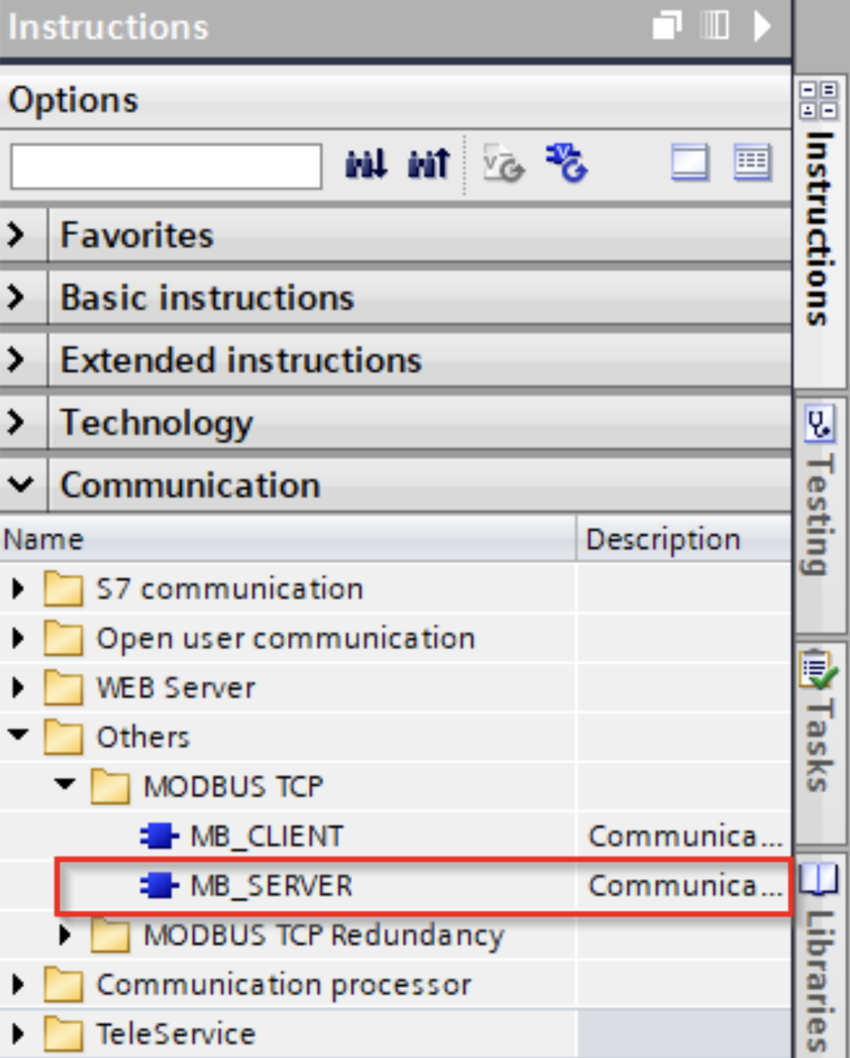
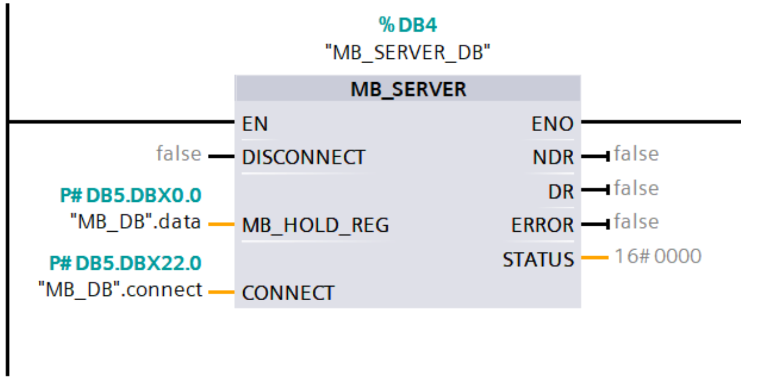
Drag the MB_SERVER instruction into your ladder logic diagram:
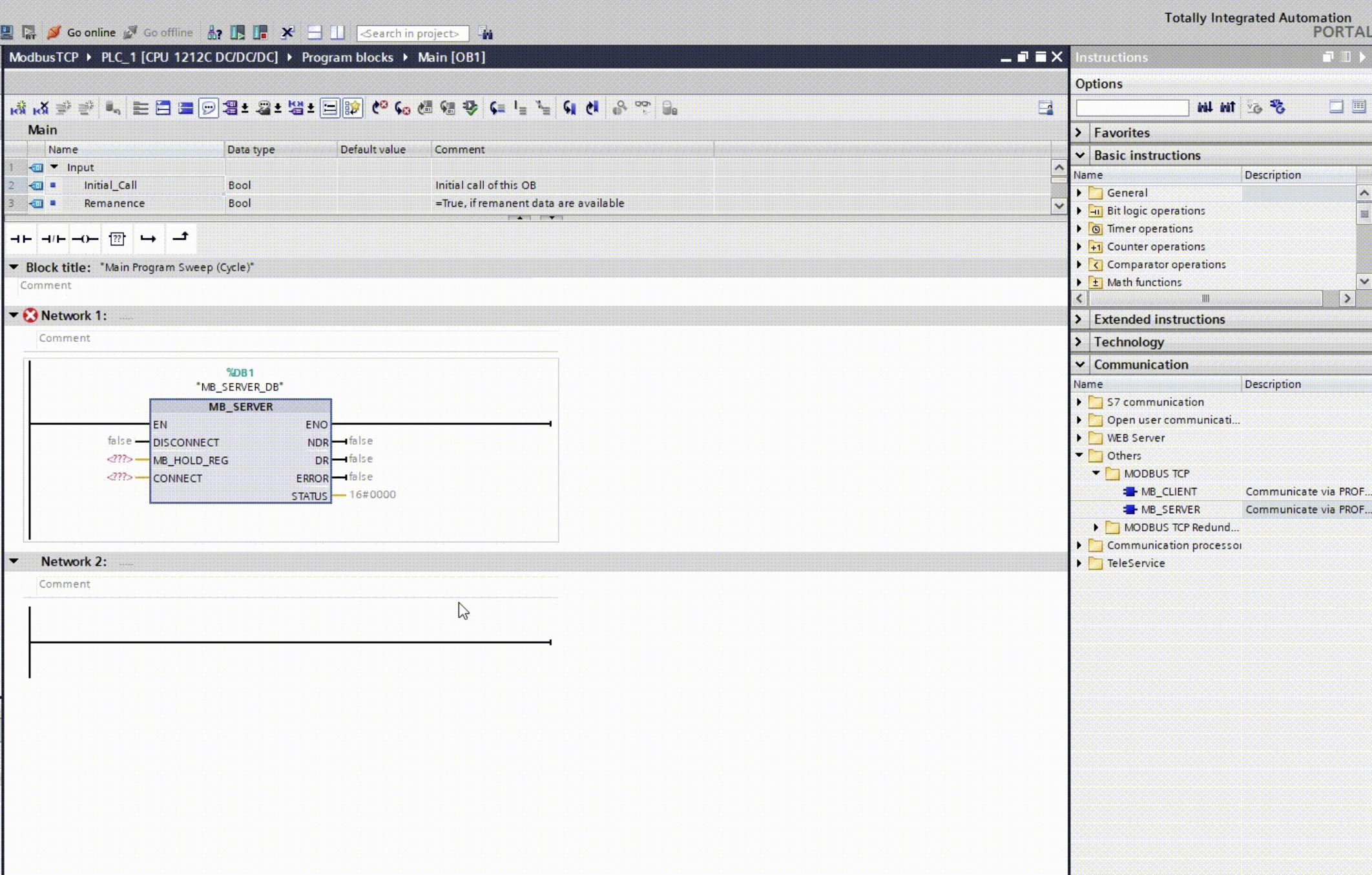
- Create a data block:
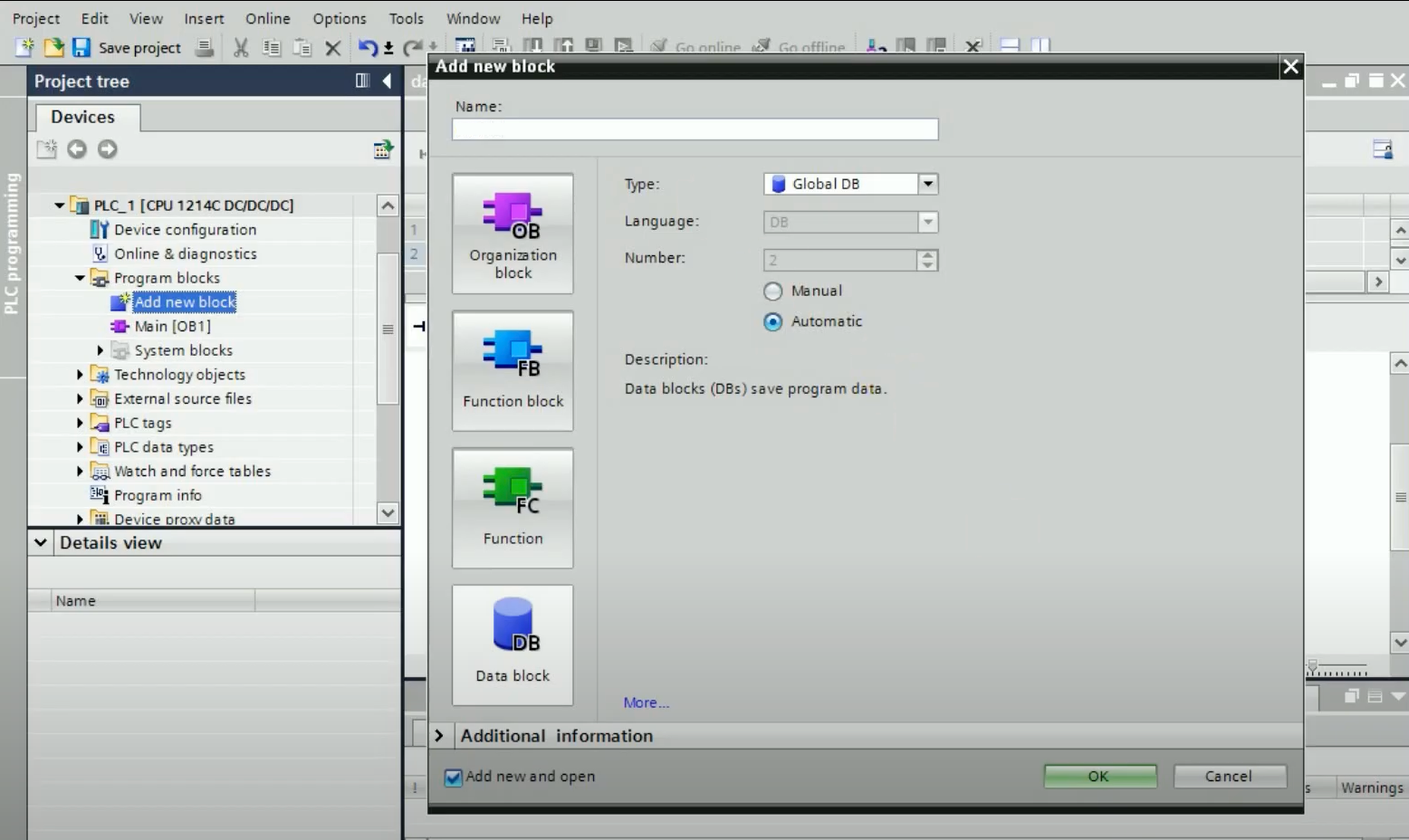
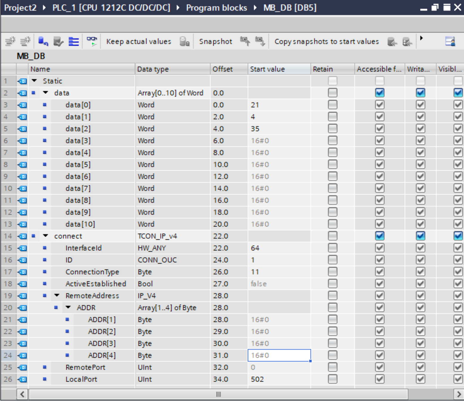
Click on the new data block, then add these two variables:
- Data: An array of type “Word” to store Modbus data (e.g., initial values such as “21,” “4,” and “35”).
- Connect: Type "TCON_IP_v4" as data type to configure the Modbus TCP server settings. Immediately, you will see a list of configuration variables appear justbelow it. Set them as follows:
- Local Port should be set to “502,” which is the default port for Modbus TCP communications.
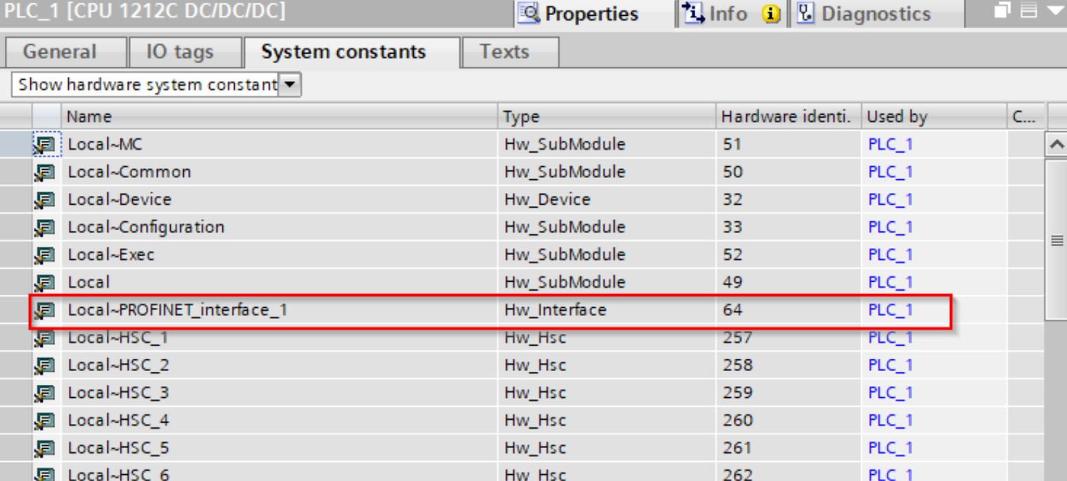
- The InterfaceID is the hardware ID of your PLC ethernet port. In TCP/IP communication we use the ethernet port, so the ID would be "64". You can find the ID in the device configuration -> system constants page:
- ID is the Slave ID, we have written “1”. Later, we'll have to use the same ID in the slave simulator.
- Connection Type should be “11” for TCP.
- Set RemoteAddress to your PC’s IP (found using ipconfig on Windows or ifconfig on Linux/Mac)
The data block should look like this:
- Lastly, point the "Data" variable to the MB_HOLD_REG field of the Modbus block, and the "Connect" variable to the CONNECT field of the Modbus block:
Now, download the configuration to the Siemens PLC by right-clicking on the PLC and selecting “Download both hardware and software”. If successful, the PLC will act as a Modbus TCP server, ready for communication.
Simulating Modbus Communication Using the ModbusClientX Tool
Reading Modbus Data Using ModbusClientX
To verify that your PLC is functioning correctly as a Modbus TCP server, use the ModbusClientX tool for simulation.
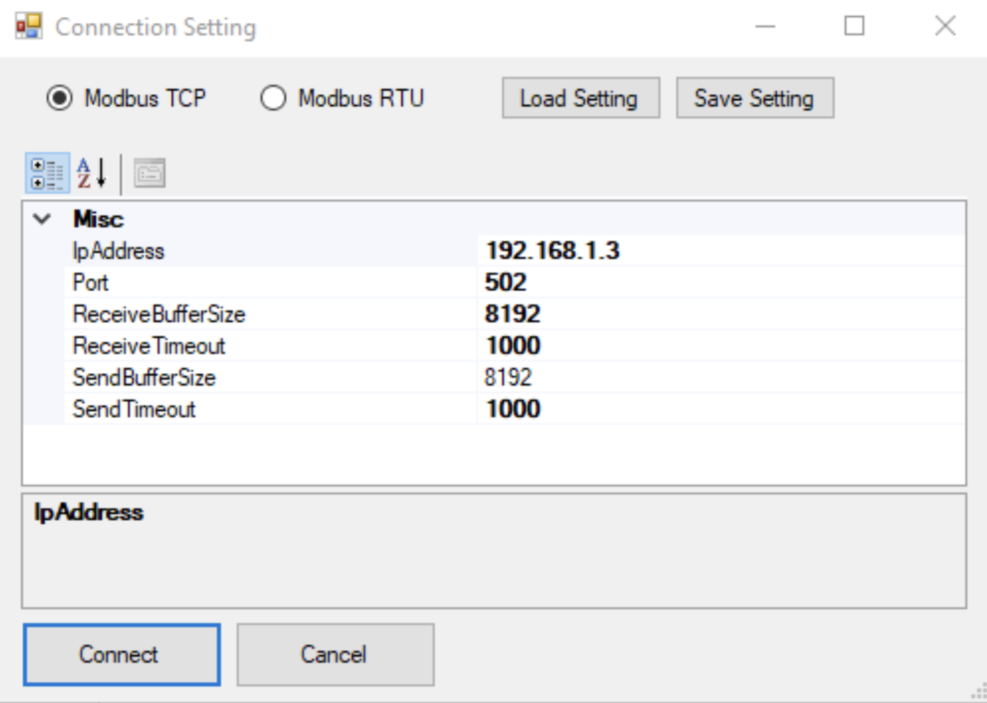
- Open ModbusClientX and select Modbus TCP.
- Enter your PLC’s IP address and click “Connect.”
- Click “Read from 0 to 9” to retrieve the first 10 data values stored in the Data array within the PLC:
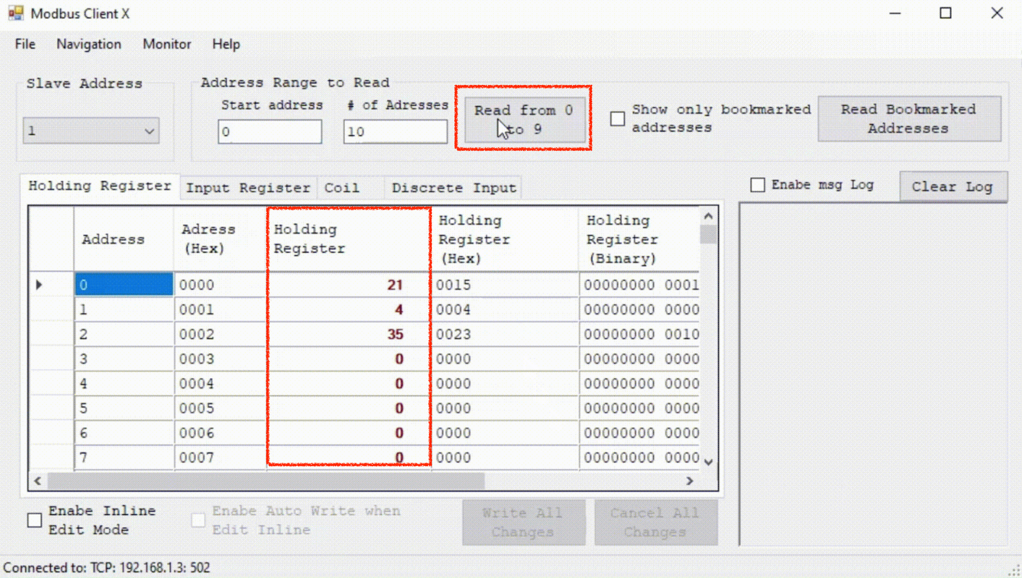
If the values you set (e.g., “21,” “4,” “35”) appear, this confirms that the Modbus TCP communication is working as expected.
Writing Modbus Data Using ModbusClientX
ModbusClientX also allows you to write data back to the PLC, simulating real-world scenarios such as industrial sensors and actuators sending data.
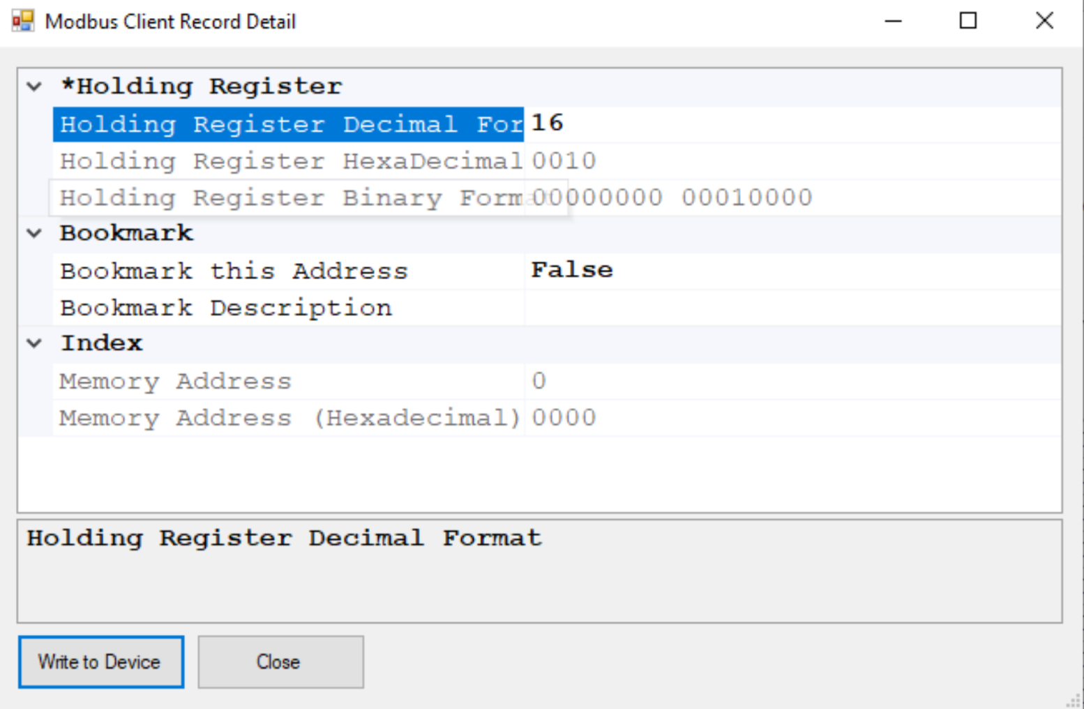
- Double-click on any value in the “Holding Register” column to open a screen where you can input new data values. Holding registers are crucial in Modbus communication as they allow for flexible data manipulation within Siemens PLCs, ensuring that data structures and parameters align for successful communication.
- Enter your value and click “Write to Device.”
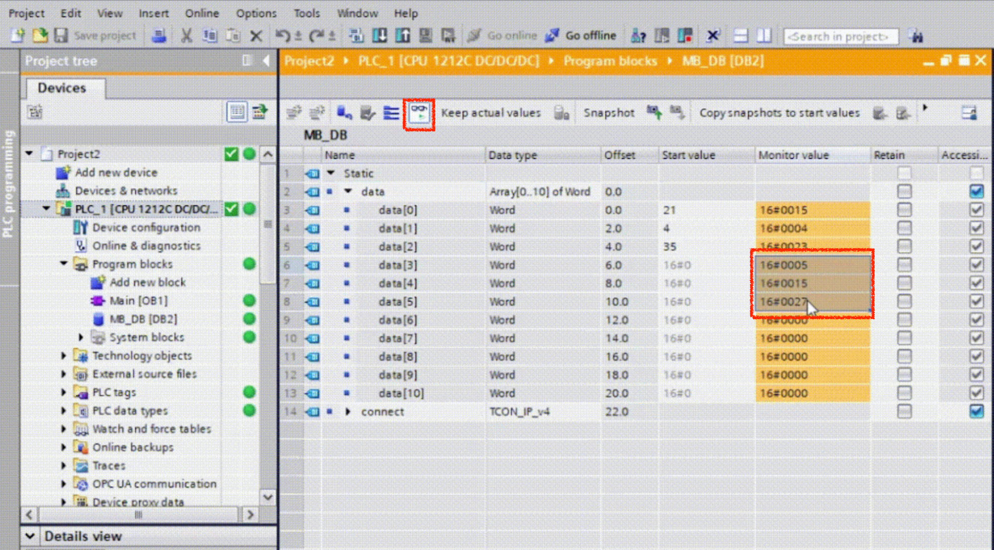
Next, return to TIA Portal and open the data block in “Monitor Mode” (click the spectacles icon). The new value will appear in the corresponding variable, confirming successful data writing to the PLC:
Using an IoT Gateway as Modbus Client to Poll Sensor Data
Once you've configured the Siemens S7-1200 as a Modbus server, you're one step closer to seamless data collection from your sensors using an IoT gateway configured as Modbus client, such as a Teltonika TRB-140, or an Advantech ADAM 6717. By doing this, the IoT gateway can continuously poll the PLC for sensor data and transmit it to an IoT cloud platform such as Ubidots, for real-time monitoring and analysis.

Step 1: Identify the Modbus Registers
First, you need to ensure that all the relevant sensor data is mapped to specific Modbus registers within the PLC. In the MB_HOLD_REG field of your data block, you’ll have defined variables that correspond to the sensors connected to your PLC. Each sensor’s data will be stored in specific holding registers, which can be read by the IoT gateway.
- Ensure each sensor’s data is correctly assigned to an individual holding register.
- Map out these registers so you know which register corresponds to each Modbus sensor or data point (e.g., temperature, pressure, flow rate).
Step 2: Configure the IoT Gateway
Now, configure the IoT gateway as a Modbus client. In the gateway’s configuration interface:
- Set the IP address of the Modbus server (the Siemens PLC).
- Ensure the Modbus TCP protocol is selected.
- Enter the port number (usually 502 for Modbus TCP) to connect to the PLC.
- Define the range of registers that the IoT gateway needs to poll. This should align with the holding registers you set up in the PLC for your sensor data.
- Set the polling interval according to your needs (e.g. every 5 minutes)
Step 3: Send Data to the Cloud or Another System
With the Modbus data successfully being polled by the IoT gateway, you can now configure the gateway to forward this data to an industrial IoT platform or an internal destination (e.g. local server) for further processing, storage, or analysis. Most IoT gateways provide options for sending data via MQTT, HTTP, or other protocols.
By integrating an IoT gateway as a Modbus client, you enable robust, scalable, and centralized monitoring of your entire sensor network, leveraging the full potential of both Modbus TCP communication and industrial IoT capabilities such as creating cloud-based SCADAs.
Best Practices for Modbus TCP/IP Configuration
Now that you know how to setup your S7 PLC to act as a Modbus server, here a few tips for a reliable and efficient Modbus TCP setup. By following these guidelines, you can prevent common communication issues and streamline both the configuration and maintenance of your Siemens SIMATIC S7-1200 PLC.
- Always use consistent naming conventions for your data blocks, registers, and variables.
- Test your Modbus TCP setup using a Modbus server simulator before deploying it in a production environment.
- Ensure your Siemens PLC firmware and TIA Portal software versions are compatible.
- Use proper IP address allocation and port forwarding if integrating the PLC into a larger network.
- Document all configurations and settings for easier troubleshooting and maintenance.
Conclusion and Next Steps
By following this tutorial, you’ve successfully transformed your Siemens SIMATIC S7-1200 into a Modbus TCP server, capable of reading and writing data to Modbus clients, such as Modbus sensors, across an industrial network. The next step is to expand this setup by integrating it with an industrial IoT gateway, enabling remote data monitoring and control over SCADA systems. Continue exploring the potential of Modbus communication to enhance your industrial automation infrastructure.
FAQs
Does the S7-1200 support Modbus TCP?
Yes, the Siemens S7-1200 fully supports Modbus TCP, enabling it to act as a Modbus server or client within a TCP/IP communication framework.
Does the S7-1500 support Modbus TCP?
Yes, the Siemens S7-1500 also supports Modbus TCP, providing advanced communication capabilities in industrial environments.
What is the default IP address of S7-1200 PLC?
The default IP address of the Siemens S7-1200 PLC is typically 192.168.0.1, but this can be changed during device configuration.
What is the communication protocol used in the S7-1200 PLC?
The Siemens S7-1200 PLC supports several communication protocols, including Profinet, Modbus TCP, and Modbus RTU.
What is Modbus TCP?
Modbus TCP is a protocol used to communicate over TCP/IP networks. It allows Modbus devices to exchange data using Ethernet-based infrastructure, commonly used in industrial automation systems.
Is Modbus RTU and RS-485 the same?
No, Modbus RTU refers to the communication protocol, while RS-485 is the physical layer used for serial data transmission in Modbus RTU setups.
What communication protocol does Siemens PLC use?
Siemens PLCs commonly use Profinet, Modbus TCP, and OPC UA for communication in industrial environments.
What is the difference between Modbus RTU and Modbus RS-485?
Modbus RTU is a communication protocol, whereas RS-485 is the serial communication standard typically used to implement Modbus RTU in industrial devices.